In order to place the laser reflection at the end of the cantilever, you must shine a laser beam on either the granite base or a piece of paper.
You can view the laser spot several different ways:
- If a probe is being replaced, first select Stage > Load New Sample to reflect the laser off the of the granite base while it is locked in the Z-stage dovetail.
- If the probe has already been removed, you may need to raise the Z-stage by selecting Navigate > Focus Surface or Microscope > Withdraw.
- You can see the laser by moving the scanner over the alignment station.
- You can see the laser spot by removing the scanner from the dovetail (without unplugging the cable between the scanner and the Dimension Icon microscope base) and holding the scanner over the granite or piece of paper.
CAUTION: Use extreme caution when removing the scanner. Hold the head firmly and do not stress the wire between the scanner and the Dimension Icon microscope base. Dropping the head will likely result in damage and Bruker factory repair.
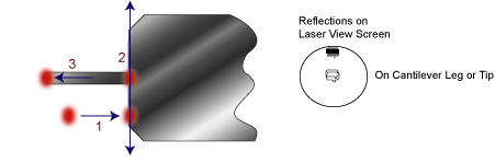
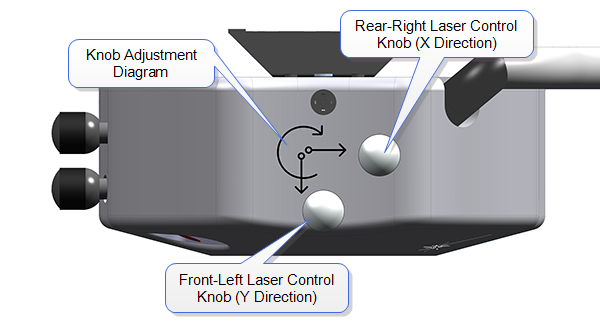
- Verify the laser beam is visible on the surface below. If it is not, turn the rear-right laser control knob counter-clockwise until the laser spot appears on the surface below.
- Turn the rear-right laser control knob clockwise to move the laser in the X positive direction until the laser spot disappears from the surface below. Turn the right-rear laser control knob counter-clockwise until the laser spot just reappears and stop turning the knob. The laser is now positioned at the edge of the substrate (see Point 1, below)
- Once the laser is positioned just off the edge of the substrate, use the front-left laser control knob to move in the Y direction (parallel to the edge of the substrate) until the laser crosses a maximum of four legs on the two V-shaped cantilevers (see Point 2).
NOTE: This occurs when moving in one direction (either up or down from end to end). If the laser is close to the substrate, you should detect four distinct occurrences of the laser spot disappearing and reappearing on the surface below.
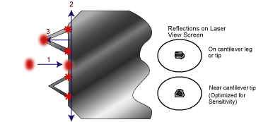
- If the laser is positioned between a pair of legs of one cantilever (laser spot on surface below) turn the rear-right laser control knob counter-clockwise to move the laser left in the X direction until the laser spot disappears on the surface below (see Point 3).
- Verify the laser is located on the portion of the cantilever connecting the two lever arms near the tip location by moving the laser on and off the cantilever, repeatedly, with an 1/8 turn of the back-left control knob. Then, place the laser back on the cantilever.
- Turn the rear-right laser control knob counter-clockwise to move the laser in the X negative direction on the cantilever until the laser crosses the tip-end of the cantilever and falls on the surface below.
- Move the laser onto the tip-end of the cantilever by reversing the direction of the rear-right laser control knob clockwise until the spot disappears from the surface below.
The laser is now on one of the two cantilevers. To determine which cantilever the laser is on:
NOTE: During this step do not adjust the back-right laser knob, or you may accidentally return to the original cantilever. Only use the back-right knob when you need to place the laser on the other cantilever.
- Rotate the back-left laser control knob in either direction until the laser disappears and does not reappear with an 1/8 turn.
- Use the same back-left laser control knob to rotate the laser the opposite direction, past the original cantilever.
- If the laser was on the longer cantilever at then beginning of this step, then the laser will not cross any other cantilever legs during this movement.
- If the laser was on the small cantilever, then the laser will cross the two longer cantilever legs.
- Select the cantilever for imaging by returning to the original cantilever, or locate the other end of the current cantilever.
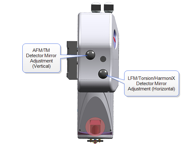
- Verify that a laser spot appears in the Dimension Icon scanner filter screen. If there is not laser spot, adjust the photodetector mirror using the photodetector adjustment knobs located on the left side of the scanner.
 Etched Silicon Tips (TappingMode)